
Background information on BITBUS
BITBUS provides a far more reliable connection than competing fieldbusses, for example those based on asynchronous communication.
You would want to program against BAPI, which is a uniform interface for the PC side, regardless of the BAPI-complianthardware underneath, be it USB, Ethernet or an add-on card. The BAPI DLL gets installed with the Windows® WDM driver. A similar mechanism is available under Linux.
BITBUS it is based on several solid standards:
- RS485 as electrical specification for reliable communication in rough environments extending up to several kilometers
- SDLC as a software protocol for compact, synchronous message transfer
- NRZI-encoding resulting in half the data rate and wire polarity irrelevance
- Simple client/server architecture
BITBUS has been defined by Intel in 1984 and was later standardized as IEEE1188.
- Why BITBUS
- Basics
- RAC/GBS
- Installation
- BAPI (/TCP)
- Specification
- Downloads
Why BITBUS?
Technically better!
BITBUS can cover large areas: 300m at high speed, 1.2km at 62.5kBit/s. Unlike others, BITBUS can use repeaters to multiply cable lengths. BITBUS can easily be isolated. Standard optoisolators (VDE0884 available) are used with no line length penalty like with buses based on bitwise arbitration.
BITBUS uses SDLC, a message based protocol with automatic error detection. Standard serial controllers like the 85C30 or Z16C32 do the SDLC protocol handling in hardware while character based protocols (asynchronous transmission) have a far lower error detection rate and critical gap timing constraints.
BITBUS uses a single twisted pair plus ground for easy cabling (compare this to fiber optics). The RS485 standard is widely recognized for its noise immunity. BITBUS uses NRZI encoding: clock is transmitted together with the data and a polarity needs not to be obeyed with the BITBUS wire pair. A faulty station or one without energy does not block the bus (compare most i/o busses).
BITBUS is simple!
Easy cabling and the simple client/server architecture opens BITBUS to people who don't want to get tangled in a network but rather apply it to their tasks. The emphasis of BITBUS is not on fancy features but on basic functionality and reliability. Concepts and use of BITBUS can easily be presented to your service and sales force resulting in high general acceptance.
These advantages have led to a wide usage of BITBUS in industry, so much that many companies continue its use long after Intel's withdrawal from BITBUS chip manufacture.
The obsolescence of the first generation i8044 single chip BITBUS controller used in many of ELZET 80's early BITBUS products forced us to look for alternatives. As BITBUS is an open protocol, it proved relatively easy in the 90's to implement the protocol on a then modern microcontroller and the Z16C32 IUSC serial controller with SDLC capability. This combo had many advantages over the i8044: the processing power of 16-bit-controllers, no limit on message lengths, low power technology. In 2003, this technology was taken to an ARM processor with built-in SDLC and then employed in the new USB, EThernet and PCIe products.
BITBUS is dedicated to distributed control, not distributed i/o, and therefore expects a real time kernel as application layer in each client. Fortunately Volker Goller wrote a modern real time kernel for the TLCS900. His message based mCAT, now in its second generation for ARM, too, conforms perfectly to the requirements of BITBUS and adds state-of-the-art support for the real-time C-programmer.
Typical BITBUS applications are:
- Plant data control: Exchange of machine status, operation times, number of parts produced. Download of product specifications
- Building automation: Send and get room or floor status from host to clients. Control lighting and climate
- Transport and conveyor belt control: Detect product markings and shift switches accordingly.
- Data logging for quality control: Report product data (weight, tolerance etc.) to host for statistical analysis.
- Inventory booking terminals: Control parts going in and out of storage.
- Distributed staff information: Make order data, quality status and messages available on graphic/character LCD throughout a factory.
- Data loggers: Collect process or environmental data at a client, store and display locally. Make current or concentrated stored data available to the host.
- Motion control: Using BITBUS based servo amplifiers, move robots and control tooling machines.
BITBUS is not well suited as i/o-bus, i.e. to connect single sensors or valves.
To the future of BITBUS:
Companies that want to continue using BITBUS because of its technological advantages, are supported by ELZET80 with development perspectives for many more years. After a cheap Ethernet gateway 2004, we expanded our product line in 2011 for example with a PCI express board for the BITBUS. Further, we are prepared for FPGA integration with a modern Cortex-M4 microcontroller if required in high performance clients.
Today ELZET80's BITBUS products are mainly used to upgrade existing installations to modern visualisation equipment, which normally happens by replacing an existing server with one of the Ethernet/BITBUS-gateways. But we are happy to help with client upgrades (machine/installation), too.
Do not hesitate to contact us if you have any product requirements around BITBUS. We will do our best to meet you expectations - ELZET80 stands for a modern BITBUS!
Basics
Though having a clear and simple structure, BITBUS cannot be handled by a typical serial controller as found in a PC, for instance. It needs a controller capable to send and receive NRZI encoded synchronous messages as used with SDLC. These controllers usually handle the complete frame inclusive of message start detection, length check and CRC calculation. The data encoding used with BITBUS reduces the frequency on line by more than 50% compared to typical asynchronous protocols, resulting in longer allowable line lengths. In addition, synchronising and CRC checking deliver a reliability that by far outperforms standard approaches.
There are 250 participants (nodes) allowed in a BITBUS network. Depending on hardware and manufacturer, the address needs to be set using jumpers, rotary switches or it might be programmed into EEPROM. Addresses 0 and 250..254 are reserved, 255 addresses the local network board processor from the master processor (source extension) and is used as broadcast address, a new IEEE1118 feature.
To keep things simple, there is only one master who originates all requests and gets replies from the slave nodes. A slave cannot transmit without being polled so there are no bus arbitration problems. As soon as the master has sent a request, it starts polling for an answer. Special very short messages are exchanged while waiting for a reply. More than one request can be sent to a slave before having a reply on the first one.
Unanswered requests are called outstanding messages. A typical slave can handle 8 outstanding messages.
Messages can be sent to 16 (8 on i8044) different tasks in a slave with task 0 being reserved for the RAC task (remote access and control interface), now named GBS (generic bus services) in IEEE1118. RAC and real-time-kernel are the layer 7 of BITBUS and support basic i/o functionality and remote user task control.
A BITBUS message basically is an SDLC message containing the BITBUS specific data as information field. SDLC is a bitsynchronous protocol defined by IBM and used very widely in all areas where data integrity is mandatory (HDLC, ISDN). The SDLC frame is handled in hardware by the serial line controller, i.e. address checking and CRC generation/detection need no processor overhead. In many implementations, the message is transferred into memory in the background (DMA) and the processor is interrupted if the transfer is complete.
Message structure
While the outer SDLC frame is filled by system software, it is the user´s responsability to fill the BITBUS message (the double framed part in the drawing) with the following information:
Length: data field lenght plus 7
Routing flags:
- MT differentiates master requests (MT=0) from slave replies (MT=1).
- SE (source extension) indicates that not the network processor is the originator of the message but a processor controlling it (for example the PC processor on a PC master board).
- DE (Destination extension) routes the message to a processor behind the receiving network node
- TR (Transmit/Receive) is a transmit/receive flag. Used internally in the i8044 only. Set to "0".
Node addressspecifies the destination (slave) 1..249
Source/destination: 4 bits each specify the task number (0..15) of the source application (i.e. visualization app. or BITBUSmonitor or ... on the master PC) and the task number at the destination (0 for RAC, other for different user tasks).
Command/response byte: tells the slave what to do. For RAC/ GBS the commands are predefined, user task commands are application specific. Contains error code on reply: 0 = no error, 80..9F are RAC error codes, others are user error codes.
The data field has a variable length from 0 to 248 bytes (0..13 on i8044). Usually the length of the expected reply is sent with the request to ease buffer management in the slave. For some RAC commands (i.e. Read I/O) there is a sequence of address/dummy bytes where the dummy bytes are filled with the data read on the given i/o address in the slave.
The CRC16 bytes and the ending flag are not part of the BITBUS message but are added by the SDLC-controller hardware.
For all standard applications, the user does not need to know more about the BITBUS internals. It is his duty to fill a buffer with the message information and to hand the buffer over to BAPI ( the BITBUS Application Programmers Interface) or the respective proprietary operating system function.
RAC/GBS task
One of the many advantages of BITBUS is it's definition of a standard command set called RAC ""Remote Access and Control interface". With the extension of the commands under IEEE1118, they have been renamed to GBS "Generic Bus Services".
These commands can be used on BITBUS slaves of all vendors. RAC/GBS is addressed as task 0 on a slave and the desired command is selected in the command byte.
I/O access structure
For the example of an i/o-command, the BITBUS message buffer has to be filled with length, routing flags, node address, S/D task numbers and the RAC command number followed by a sequence of port addresses and data bytes: Add1, Data1, Add2, Data2,..
When it returns, the command byte is filled with an error code and the data bytes contain updated port data.
Memory access structure
In the case of memory commands the begin of the buffer structure is like with the i/o access structure, however the data field starts with an address pointer (high byte, then low byte) followed by the memory data to be written or dummy bytes with read commands. The length field is memory data bytes plus 9 (standard 7 + 2).
IEEE1118 address extension: To allow for memories greater than 64K (essential for processors like TLCS900 or MC68xxx with a large linear address space), address pointers can be extended as follows: Use BFH as command byte, then put into the first two bytes of the data field the address extension the upper 16 bits of a 32bit address. The third byte of the data field gets the command byte followed by the LSW of the memory address (for memory commands). Address extension also works on i/o-commands, as these are based on a 256 byte i/o address space, the extension is the upper 16 bits of a 24 - bit address, however.
Function IDs
To allow for tasks to be independent of a certain task number they are assigned by the system, function IDs are supported. In the task header (for iDCX51 and mCAT tasks) there's an entry for a function ID. The RAC/GBS-function GBS_GET_FUNC returns a list of 8 or 16 bytes with function IDs (sometimes even 32 as the 'DE'- bit is used by some manufacturers to extend the possible number of tasks). The first byte is the ID of task 0 (usually it contains 01, as this is the ID of the RAC/GBS-task), the second that of task 1 and so on. If FF is returned, there's a task with no function IDs, while a '0' means there is no task. BITBUS/IEEE1118 allows codes 80 to FE for user function IDs.
Using slave tasks
Most BITBUS slaves are equipped with a real time multitasking kernel where messages can be sent from the master to specified slave tasks. These tasks are addressed exactly like the RAC/GBS task except that the destination task number isn't 0 but the number of the desired user task (which can be found out from the master using the mechanism described above. In the table below, the function type specifies the structure of the data field with I for the I/ O-type structure and M for memory accesses as described above. C are control commands that have their specific data explained in the command description.
RAC/GBS Commands:
| Command code | Command type | Command description |
| 00 | C | GBS_RESET Resets the slave (the only function without reply) |
| 01 | M | GBS_CREATE Creates and starts a task. Data field contains a pointer to the task header, MSB first. (16 bit + BF extension) |
| 02 | C | GBS_DELETE Deletes a Task. Data: task number as only data byte. |
| 03 | C | GBS_GET_FUNC Get function ID (see above) |
| 04 | C | GBS_PROTECT Disables remote access commands Data: 0= no protection, 1= protect memory, 2= write protect. |
| 05 | I | GBS_READ_IO Reads from port addresses. |
| 06 | I | GBS_WRITE_IO Writes to port addresses. |
| 07 | I | GBS_UPDATE_IO Writes and re-reads the port addresses specified. |
| 08 | M | GBS_UP_DATA Uploads a random memory block from the slave. |
| 09 | M | GBS_DOWN_DATA Downloads a memory block |
| 0A | I | GBS_OR_IO Logically ORs data in i/o ports with the mask given as data bytes. Re-reads the port. Used to set some bits. |
| 0B | I | GBS_AND_IO Logical AND used to reset bits. |
| 0C | I | GBS_XOR_IO Logical XOR used to toggle bits. |
| 0D | I | GBS_WRITE_IRAM Writes to internal RAM (hardware specific memory block). In the case of mCAT, these commands cover a predefined memory block. |
| 0E | I | GBS_READ_IRAM Reads from internal memory. |
| 0F | I | GBS_GET_INFO Returns hardware and task information (see below) |
| 11 | M | GBS_UP_CODE Uploads code from the slaves memory. Same as UP_ DATA with processors that do not distinguish between code and data spaces. |
| 12 | M | GBS_DOWN_CODE Downloads code to slaves using special EEPROM/ Flash-Eprom memory write procedure |
| 15 | C | GBS_GET_TIME Returns data structure (see GbsTime) with date and time info. |
| 16 | C | GBS_SET_TIME Sets time (see bitbus.h) |
| 17 | C | GBS_SUSPEND_TASK Suspends the task with the number given as only data byte. |
| 18 | C | GBS_RESUME_TASK Resumes the task (number) |
| 1A | C | GBS_GET_TASK_ID Returns task id for function id entered (similar to GBS_GET_FUNC but for one id only). |
| 20 | M | GBS_FLASH_ERASE Erases a flash-EPROM memory block. Uses extended addressing and 32bit data length. |
| 21 | M | GBS_FLASH_GET_ID Returns 32bit Flash- EPROM type code in ext. addressing message. |
| 22 | C | GBS_EEPROM_WRITE Writes into the serial EPROM with 16bit addresses: 16bit data; 16bit adr.; 16bit data; 16 Bit adr.; |
| 23 | C | GBS_EEPROM_READ Reads EEPROM (Same structure as WRITE). |
| BF | GBS_EXTEND_ADDR Address pointer extension. See memory structure text for details. |
RAC/GBS error codes:
| 00 |
GBS_ERR_OK Okay, no error. |
| 80 | GBS_ERR_NO_DEST_TASK Task does not exist. |
| 81 | GBS_ERR_TASK_OV No space for more tasks. |
| 82 | GBS_ERR_REGISTER_OV No register bank available. |
| 83 | GBS_ERR_DUPLICATE_TID New task has function ID that already has been assigned. |
| 84 | GBS_ERR_NO_BUFFERS Buffer pool exhausted |
| 86 | GBS_ERR_BAD_TASK_DESC Task descriptor (ITD) is not valid |
| 87 | GBS_ERR_NO_MEMORY No more memory available |
| 90 | GBS_ERR_TIME_OUT IEEE1118 slave not available |
| 91 | GBS_ERR_PROTOCOL Unspecified error. |
| 93 | GBS_ERR_NO_DEST_DEVICE No extension available (see "Routing flags") |
| 95 | GBS_ERR_PROTECTED command protected (see command 04) |
| 96 | GBS_ERR_NO_GBS Unknown RAC/GBS command. |
| 97 | GBS_ERR_BAD_COMMAND_LEN Command length does not match command specification. |
</>
System Info
The RAC/GBS command 0F (GBS_GET_INFO) provides information on the software in the node as follows:
|
Data Bytes |
Content |
| 0..5 | 6 ASCII characters name ("i8044", "mCATV2") |
| 6,7 | ASCII version number ("2.1") |
| 8 | i8044 memory info, not supported by mCAT |
| 9 |
Max. message size supported by this node |
GBS Time Services System Info Structure
typedef struct {

   BYTE zone,   /* TIME ZONE : 0 = GMT, 8 = PST */

   offset,      /* TIME OFFSET : 0..59 MINUTES */

   day_of_week, /* 1..7, MONDAY = 1. */

   year,        /* 1980 = 0, 2235 = 255. */

   month,       /* 1..12, JANUARY = 1. */

   day,         /* 1..31. */

   hour,        /* 0..23. */

   min,         /* 0..59. */

   sec;         /* 0..59. */

} GbsTime;
Installation
BITBUS installation
Although BITBUS has proved to be rather tolerant about cabling, RS485 definitions require some precautions that should be obeyed for optimum performance:
Cable
RS485 uses a balanced differential signal pair where one wire (usually named Data+) is on 5V (nominal) to signal TRUE data while the inverted wire (Data -) is on 0V and vice versa for FALSE data. The advantage of using a differential line is that a spike induced to the line ideally shifts both wires with the same voltage amount resulting in no change in the voltage difference between the two wires.
For good operation the two wires have to be twisted. The cable is available as so called "twisted pair cable". The voltages are allowed to float for a certain amount (-7 to +12V) against ground. Nevertheless there should be a possibility to reference against ground which calls for a third wire SIGNAL GROUND. There are many RS485 installations that just use the twisted pair but nobody would guarantee a groundless cabling. Usually a cable with two twisted pairs is used with on pair used for ground. A third pair is necessary in BITBUS nets using repeaters for the slave segments (the segments on the slave side of the repeater). This pair (RTS+/ RTS- ) drives the amplifier signal direction input to switch from the standard (out to all slaves) to input if a slave in the segment wants to transmit.
Termination
RS485 calls for termination of the signal lines at the extreme ends of the cable. A 120Ohm resistor between the wires of each pair gives the proper termination for the RS485 drivers. The cable should match this value as good as possible, i.e. have a characteristic impedance of 120Ohm or more. DB9 connectors with termination resistors are available from most manufacturers.
An even better way to terminate is to connect separate resistors from the supply voltage to the RS485 lines like described in the BITBUS book to take the lines to a defined idle state. This, however, can only be done inside the board where supply voltage is available. Thus many manufacturers supply switchable termination on their boards.
Shielding and earthing
Although shielding is not required by the BITBUS specification, all industrial applications should use a shielded cable. The cable screen should be connected to earth (foreign ground) on one side of the cable only (to prevent ground currents flowing through the BITBUS cable).
The resulting recommended cable is a 3 pair 0,25mm² twisted pair stranded wire with overall screen. It is called LiYCY(B) 3x2x0,25mm² in Germany.
Repeater operation
A standard RS485 driver like the 75176 drives 31 receivers on the twisted pair (there are advanced designs like the 75LBC176 that drive more than 50 receivers). BITBUS conservatively specifies 28 slaves. They all have to be within the cable length specified for the given bus speed (300m for 375kBit/s and 1200m for 62,5kBit/s, also specified well on the safe side). There are no stubs allowed for a node (i.e. it must be connected immediately to the bus line and not with a long cable to the bus. To allow for stubs or more slave devices (BITBUS logically addresses 250 nodes), repeaters can be used. A repeater is an amplifier, usually using a standard RS485 receiver and transmitter. It is part of the network just as any other BITBUS node (usually with electrically parallel input and output connectors) and has a third connector on the amplified side (which is the far side as seen from the master), the so called slave side.
As an amplifier cannot drive both data directions at the same time (BITBUS is halfduplex, i.e. uses the same wire pair to transmit to the slave and to receive from the slave), the transmit enable signal of the slave (RTS) is used to invert the amplifier direction that usually is outward only (master to all slaves). This signal is necessary only in the slave segments as the master doesn't need to know about it, just the repeaters on the way to the master. BITBUS allows two repeaters in line between the master and any slave (but up to 28 with their master side in one segment) at 375kBit/s. Repeaters can thus be used to establish many stub lines.
BAPI
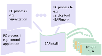
The BAPI standard (pdf) defined by the BITBUS European Users Group (BEUG) offers a uniform way to access different BITBUS boards of one or more suppliers. The idea is to support heterogeneous environments allowing a mixture of boards of various manufacturers. ELZET80 has implemented BAPI drivers since their inception and meanwhile offers BAPI compliant drivers for USB, PCIe, PCI, ISA, PC/104, and PCI104 boards, supporting all current Windows® versions (to Win7/64) and Linux. ELZET80's driver for Windows comes as a DLL that can be linked to nearly all programming languages and visualisation tools.
Programming against BAPI is pretty straightforward: After selecting the board with BitbusOpenMaster() it essentially requires you to prepare a BITBUS message and hand it over using BitbusSendMsg(). The processor on the BITBUS board will then send this message to the slave you addressed it to and wait for its answer - while your program should call BitbusWaitMsg() to get the answer. There are of course some error handling and timeouts advisable, but in essence that's all. Most people wouldn't start sending more messages out before an answer was received, although ELZET80's BITBUS drivers allow 6(8) "outstanding messages". The BAPI driver serves up to 6 boards, i.e. multiple BITBUS networks from one PC. It also allows up to 16 simultanuous applications to access the same board.
BAPI over Ethernet: BAPI/TCP
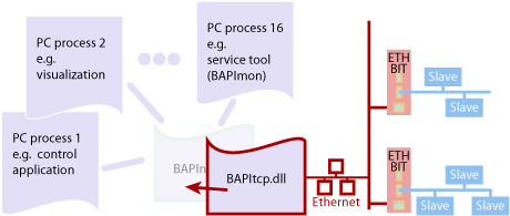
To allow seamless transitions to Ethernet, BAPI/TCP has been approved a BEUG standard in 2000. Without adding complexity, a BITBUS message gets wrapped in a TCP/IP message and is sent to a BAPI/TCP server running as a process on ETH/BIT, TSM-ARMCPU or other Ethernet-enabled ELZET80 hardware. The BAPI/TCP server simulates an IPC-BIT board - delivering the messages to the addressed slave and returning the answer via TCP/IP.
To make the Ethernet transition even invisible to the application software, there`s a BAPITCP.dll for Windows® that does the TCP wrapping and communication with the BAPI/TCP server - or, to be more precise, with up to 6 servers to fully simulate a local BAPInt.dll. If you rename the BAPITCP.dll to BAPInt.dll, your applications won't notice the exchange of the transport layer and continue to work over Ethernet. A tool is provided to assign a specific server hardware IP to a logical board name like BBUS0 as required by the BAPI protocol.
The BAPI/TCP server opens up BITBUS to every operating system supporting communication over TCP/IP sockets. You just have to assemble a standard BITBUS message, wrap it into TCP/IP as described in the BAPI/TCP document and send it to a previously opened port 8044 on the BAPI/TCP server hardware.
Specification
BITBUS/IEEE1118 specifications
| Type: | Master/slave network with synchronous SDLC message transfer. 248 bytes net data capacity. |
| Structure: | Bus, terminated on both ends. Stubs and extensions are available using repeaters. |
| Medium: | Twisted pair (one pair, 120Ω impedance) plus signal ground and shield. On the slave side of repeaters, a second twisted pair (RTS) is required for transmit direction reversal. |
| Electrically: | 0/5V differential signal as defined in RS485. |
| Protocol: | Self-clocked bit synchronous NRZI encoding. Each message is wrapped in start and stop flag bytes and contains address as well as a 16 bit check sum (CRC). |
| Data rate: | 375kBit/s or 62.5kBit/s. Some of the ELZET80 boards support 750kBit/s and 1.5MBit/s, too. |
| Nodes: | 28, to be extended to 250 with repeaters (28 each repeater). Data rate limitation to 62.5kBit with 2 repeaters in series (for length extension). |
| Length: | 300m (~yards) per segment @ 375kBit/s, 1200m @ 62.5kBit/s, conservatively specified. |
| Connector: | 9 pin Sub-D |
BITBUS' position in the network hierarchy: Use Ethernet for mass data movement and sensor buses like AS-i to access individual sensors.
BITBUS moves medium size data blocks between autonomous nodes (distributed control). BITBUS uses common cabling and allows a wide extension.
Downloads
BAPI

BITBUS API as defined by the Bitbus European Users Group. Describes how to open access to the hardware and how to construct the message structure for transmittion and reception of BITBUS messages.

BITBUS sample program LineTest. BapiwLT is named a line test program as it continuously sends out GET_NODE_INFO requests to a slave and counts the correct answers. Every typical BITBUS slave should answer to these requests.
For basic operation with ETH-BIT.., you'd first have to assign the IP-address to a logical station name like BBUS0 with the supplied tool. Next you call the bapi.dll function BitbusOpenMaster, referencing this BBUS0 and further down use the standard functions like BitbusSendMsg. From "cycle++" on (at about line 160ff of the example), you can learn how to fill the message buffer with data.
BAPI/TCP
BITBUS over TCP/IP. Official BEUG proposal for Ethernet transport.

BAPI/TCP-server: ELZET80's implementation of and extensions to BAPI over Ethernet.
BITBUS specification
Intel's original specification of BITBUS as searchable .pdf download. Frame and message formats, RAC commands, function IDs, mechanics. Advanced use documentation.