
PER-EVA900
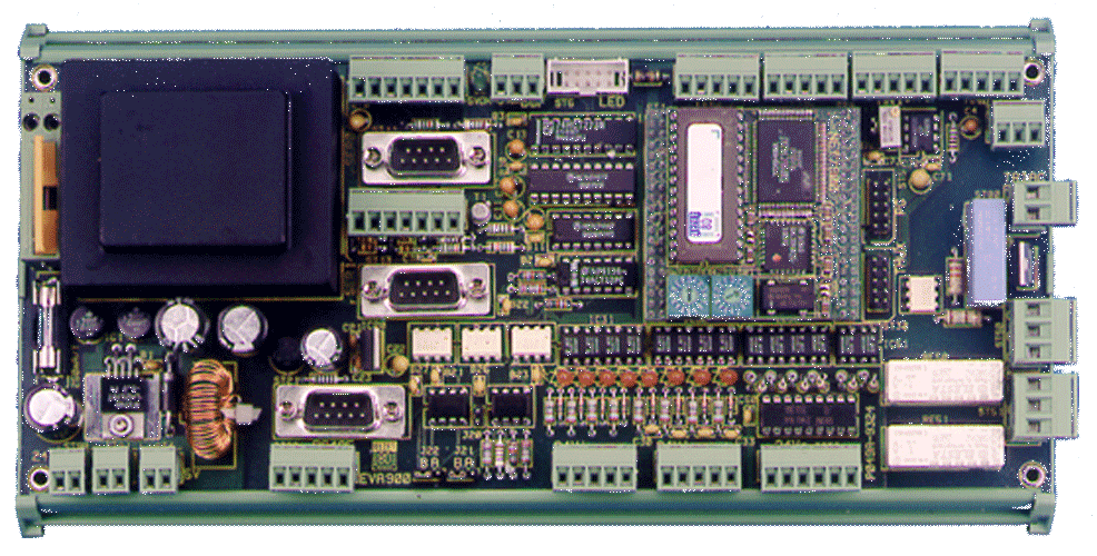
EVA900 is an evaluation board for the NET/900H controller module. It includes power supply, 24V i/o, relays, serial line drivers and more. Some say it's rather a universal control computer than an evaluation device.
- Mains power supply (115/230V) with four output voltages including 24V for small external loads
- Eight 24V optoisolated inputs, four of them onto TI4...TI7
- Four 24V optoisolated outputs, source drivers with 200mA load
- Two relays SPDT 230V/8A
- Two RS232 drivers for SER0 and SER1, DB9 and screw terminals
- High speed optoisolated RS485 (BITBUS) drivers for the IUSC
- Precision voltage reference for analog inputs
- Three TTL counter inputs multiplexed with the 24V input TI4
- Input to TI0 for tv-style infrared remote control detector RC5
- Three to six outputs for serial load 4-digit 7-segment displays
- Stepper motor ports without power driver on 10-pin header connector
- LED indicators for power and all 24V inputs
- Prices
- Details
- Installation
Prices
on request
EVA900
Board as described
on request
GEH-EVA900
Rail-mount cradle for EVA900
on request
SFT-MCATEVA
mCAT with predefined user task that makes all i/o incl. RS232 accessible from the master. Runs as task under mCAT. Source is provided. Quantity pricing available.
Software
For further informations look at e.g. NET/900H
Details
EVA900 is 250x111mm in size (or about 10 by 4 inches) and fits into a rail mount cradle for industrial use. Almost any connection uses "Combicon" pluggable screw terminal strips.
The power supply delivers four output voltages:
- 5V as system voltage for NET/900H and the drivers on EVA900
- isolated 5V for the RS485 line
- 14V unregulated as support voltage for external analog sensors
- 24V to drive the internal relays with about 200mA externally available for feeding the 24V inputs and one or two valves or external relays.
Solder jumpers permit operation on 115V instead of the standard 230V AC. The primary and the 24V output are fused. To operate the internal relay, an external connection between the supply and the 24V outputs must be provided.
The eight optoisolated inputs are split into two groups of four that are isolated from each other.Four are standard inputs to P24 to P27, four are connected to the timer and interrupt inputs TI4 to TI7. The connection to TI4 can be multiplexed with three TTL-level inputs on header connector "TMUX". TTL level counting will most often be used for sensor conditioners that output a frequency.
Four of the 8 outputs of an integrated 24V source driver are used for general purpose outputs and two to drive the internal relays. The driver is optoisolated from the processor and feeds a maximum of 200mA from a 24V source applied to the circuit into a grounded load. It directly drives standard valves and relays that usually take around 100mA each. The outputs are connected to the timer outputs of NET/900H.
The two relay on board have an optoisolated 24V drive to minimize inductive feedback to the processor circuit. Their change-over contacts are capable of switching 8 amps at 230V mains voltage. Creepage distances on the board and inside the relay conform to industrial standards.
A TRIAC output can be used to test dimming with the processor. It's a snubberless TRIAC that is capable of 16 amps at 230V although we specify only 3 amps on EVA900 (no heat sink). It's driven by P32 using a TRIAC-optocoupler.
A handshake pair has been added to the RS232 drivers on SER0 and SER1 using standard port bits. As a third signal, DTR is fixed to active state if power is applied. The RS232 lines can be accessed on 9-pin D-plugs with AT-like pinout and on screw terminals.
The IUSC serial controller on NET/900H is driven by an optoisolated RS485 port. It is configured for the half-duplex BITBUS network and the RTS-signal (used to switch the transmitter on) is sent onto a separate network line-pair. Alternatively, the RTS driver can be used as data receiver in full duplex applications, while maintainig internally the driver enable by means of RTS (P7/TxCP is used for RTS on the IUSC).
Analog inputs 0..3 are accessible on four screw terminal connectors. The ADC's input span is 0..5V against analog ground. Three voltages are available on each of the 5-pin connectors to help generate the input voltage: 5V regulated processor supply, 5V analog reference voltage, and 14V unregulated, choke filtered supply. Reference voltage is supplied for variable resistance sensors. As the maximum load for the reference generator is 20mA, the sensors connected to it should have a minimum resistance of 2 KOhm. An external sensor usually needs more than 5V to output a 5V- signal, that's why 14V are presented on the connector.
So-called "process current signals" with a 4..20mA current range can be measured by using a shunt resistor of 250 Ohm across the input. Two-wire-transmitters such as the AD693 however, cannot drive that load from low voltages. If, for the reason of isolation, 24V shall not be used to supply the transmitter, a maximum load of 100 Ohm is allowed for a 14V supply. The resulting input voltage will be 0.4 to 2V which still gives more than an 8-bit resolution.
The RC5 input is a digital input to timer 0 that has a few components added to connect the SFH505/506 IR-receivers directly. These sensors will give an active low bit stream if activated from a tv-style remote control unit with RC5 encoding.
Similarly, the DCF77 input uses P36 for reception of timing signals from a time standard transmitter located in Germany and available about 1500km around. A receiver appropriate to drive the DCF77-input will give a low active TTL- level signal.
In order to minimize the number of i/o-pins necessary to drive LED-displays, serial drivers like the MM5450 are available to drive 34 LED's, enough for a four-digit seven-segment display. They have the structure of a shift register and need three lines only: clock, data, and enable. The enable signal can be used to multiplex the clock and data lines to as many drivers as enable lines are provided. A port external to NET/900H and accessed via CS0, outputs clock, data, and three enable signals. They are available together with three free ports of the IUSC and 5V at a header connector "LED". A four-digit-module is available from ELZET80, see 7SEG4.Up to six displays can be operated by using that connector. The latch used to drive the port is also used to generate the select signals for the timer-input multiplexer and the RTS signal for serial port SER0.
The PG 00..03 and 10..13 pulse generator outputs usually drives stepper motors. Due to the diversity of the drivers for stepper motors, they have not been integrated into EVA900. Instead, a 10-pin header connector allows flat cable connection to external drivers or to use the PG port as universal i/o-port.
Part of the NET/900H support diskette is an initialization program for the i/o on EVA900.
Software:
mCAT Version 1.x for NET/900H is the operating environment for assembler or C programmers on EVA900. Please see programming concepts for a description. A predefined user task for EVA900 is available separately to allow operation from the BITBUS master with all EVA900 i/o with no programming on EVA900 side. Serial lines are supported by buffered interrupt drivers. When using the special version of EVA900 for NET/900H+, mCAT version 2 can also be used on EVA900.
Available only on NET/900 (not NET/900H+) is a powerful little BASIC interpreter that supports all hardware features of the EVA900 (see NET/900H description). Most of the features of EVA900 are also supported by the N9MON monitor program. For those who require a monitor with trace possibilities, AMON9 is available (see NET/900H).
Installation

Installation manual PER-EVA900