
BITBUS PCIe
The IPC-BIT is a series of network boards for BITBUS server or client stations. PCI-express are boards available for the most important PC bus systems. The use of PCI is possible with an adapter PCIe to PCI. The boards are supported by uniform drivers for the operating systems Windows®10, Windows®2000, XP, Vista, 7 and 2008 Server. 32-Bit- and 64-Bit-versions of Windows® are supported. The IPC-BIT is the result of more than 34 years of experience with BITBUS master cards - resulting in easy installation and well known ruggedness for industrial applications.
- Isolated RS485 interface with SN75LBC176 drivers and industrial grade line protection
- BITBUS operation with unlimited message lengths and baudrates from 62,5kbit up to 1,5Mbit/s self clocked.
- Full BITBUS message lengths (249 Byte).
- Buffer for 8 waiting messages per client.
- Modern microcontrollers with possibility for a Flash update.
- Per board up to 16 PC applications in parallel.
- Endpoint termination selectable by DIP-switch
- Driver software with bapi standard application interface is available for all modern microsoft operating systems and Linux.
- Prices
- Details
- Installation
Prices
on request *
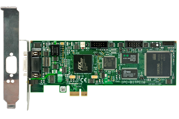
IPC-BIT<PCIE
PCI board (PCI express) with low resolution (64,4x169mm) with isolated RS485 port. High front panel optional.
* all prices in EUR ex works (+VAT/MwSt inside Germany)
Details
The IPC-BIT900 boards together with the WDM driver provide top performance BITBUS operation: Unlimited message lengths, speeds from 62.5 kbit/s over 375 kbit/s to 1.5Mbit/s, handling of outstanding messages, FIFOs to the BITBUS and to the PCinterface, firmware in Flash Eprom for easy updates, master and slave operation.
The main difference - and advantage - of BITBUS over competing fieldbusses is the use of the synchronous SDLC in contrast to the usual asynchronous protocol. Assembly and monitoring of the complete message frame including flags and CRC is done in the serial controller's hardware, which frees the processor for higher layer tasks. Using only one RS485 wire pair requires data and synchronous clock to be transmitted as one mixed signal. This operation also allows the inversion of the data pair without any problem. At the receiver end the clock has to be regenerated from the encoded signal, the PC-typical 16C550-type-controllers do not support synchronous transfers and no DPLL clock regeneration. ELZET80 uses the Zilog Z16C32 IUSC, a very high performance serial controller for both synchronous and asynchronous protocols. It not only supports SDLC and NRZI but has built-in 32 byte FIFOs for both directions and an intelligent DMA controller. To use an IPC-BIT900 board for asynchronous operation would, however, require custom software. Your inquiry is welcome.
The line side of the Z16C32 is coupled via 10MBit/s optocouplers to SN75LBC176, a low power consumption, high output capability successor of the standard 75176. A data and an RTS line are driven to allow external repeaters (that need to be switched in direction via the RTS signal). Alternatively the two transceivers can be used (jumper selectable) to operate full duplex lines (separate lines for receive and transmit) which are being used in point to point connections or for example in the DIN-MESSBUS fieldbus. A DC/DC-converter supplies isolated voltage for the drivers so the RS485 side is electrically decoupled from the PC side. Transient suppressor diodes are used on all lines to protect the drivers.
The RS485 line gets tied to a defined level by resistors against the isolated voltage if the line is idle. Bus termination can be activated by the DIP-switches, if the board is at the physical end of the bus. For users requiring external clocking, special versions are available for the bus systems ISA and PCI.
A TMP95C061 has been selected as the network processor because of its compatibility to existing BITBUS products running with the mCAT real time kernel using TLCS900-family processors. It is a 16-bit microprocessor running at 24.576 MHz. To save on space the RAM is only accessible 8 bit wide, the EPROM with the program code is addressable in full width (16 bit). The module is provided with 128K RAM and 1M Byte Flash, optionally the board can be delivered with 512K RAM. The BITBUS driver is integrated into the mCAT firmware in manner that allows downloading user application tasks into RAM or Flash- EPROM. These tasks are reachable from the BITBUS and their function code can be identified using RAC/GBS standard procedures, see BITBUS basics. This allows writing master applications in firmware that poll for instance all nodes for data preprocessing or alarm signalling without requiring the PC application to act.
Communication between PC and the master board is sped up by separate FIFOs for reception and transmission that both take at least one complete BITBUS message of 250 bytes. Real-time wise both sides are thus fully decoupled. The FIFOs are attached to the network processors DMA. PC interrupts can be signalled on lines between 3 and 15. The selection gets done by software, on the PCI board the Windows®-Plug&Play mechanism does the interrupt assignment. A large serial EEPROM saves configuration data like network speed (62.5, 375, 750, or 1500kBit), the node address, and a user size limit on message length. In interaction with mCAT based ELZET80 slave nodes hence a complete network may be switched to for example another speed by executing the set speed command from BAPIMON.
For safety-critical applications, the built-in relay with changeover contacts can be used to signal an emergency state: Usually one would create a local task to sum up all possible error conditions and keep the relay active until an error occurs. The relay is gated with RESET in a way that pressing the PC reset key, issuing a RESET command to the board or a local watchdog event all will deactivate the relay in addition to the supervisor task.
Front panel indicators show transmitter activity (yellow) and a user programmable LED (green, blinking at 1Hz with standard software).
The two internal serial ports of the TMP95C061 are taken out to 10pin header connectors for which mating RS232 level shifter modules are available. These "PER-IF232"-modules are small boards mounted to a 9pin Sub-D connector for front panel attachment. The use of these modules opens the path to local peripherals for master tasks or to the mCAT monitor for diagnostics.
The BITBUS driver is integrated into the mCAT in such a way that user-defined tasks can be loaded down into the RAM or the Flash EPROM with mCAT standard tools. These tasks are accessible via the BITBUS and can be identified via the BITBUS function code. This makes it possible, for example, to program applications that poll all BITBUS nodes and pre-compact data or respond to alarm signals without the intervention of the PC application software. The full programmability also opens the use for completely different RS485 communication tasks, also for customer specific protocols.
Installation
The installation manuals provide technical details for implementing the unit. Please note as well the information on driver installation, e.g. WDM driver.

Installation manual for BIT-PCIe